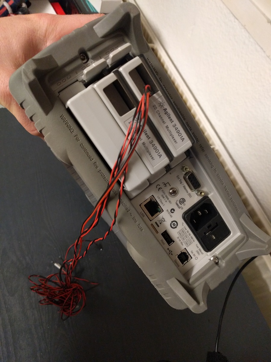
Go back to your first schematic and start simple and build on what you know already to complete the larger picture. The new signal routing architecture transforms it from a pure. I would recommend doing every command manually first and look at the measurements displayed on the 34970A and convince yourself that they make sense. Im pleased to present the 2011/12 edition of the Agilent Test and.

Unless you are trying to measure a short? But if you are able to use the text commands you should be able to follow one of the examples that Agilent has provided in my links above.ĭon't feel bad about not being able to read relay ladder logic or not knowing how a relay works, it is rarely taught in school anymore but used heavily in test and automation.Īs Dennis pointed out if you are trying to measure current on the +12V you need to move that signal to the higher channel on the 34901A not on CH6 as you have it.CH22 maybe. You are also on your own with modbus since I'm not familiar with it.
Agilent 34972a the signal path manual#
For slot 300 (34907A) you are going to have to read the manual since I have not used this card. The channels for programming slot 100 (34901A) CH1, CH2, etc. I'll assume that the 34901A is in slot 13A is in slot 200, 34907A is in slot 300. Look on the back of the 34970A and you will see 100/200/300. Looks like you are multilingual from one of the corrections.German? Combine that with scan rates of up to 250 channels/sec, and you’ve got the speed and accuracy you need to get the job done right the first time. Stored parameters can also be used for compensation to enhance accuracy during RF measurements.Just to make you feel better the first time I used the 34970A I was confused and still don't understand all the wonderful features it's capable of. The 34970A/34972A features 6 digits (22 bits) of resolution, 0.004 basic dcV accuracy, and ultra-low reading noise. If a specific performance parameter is critical, such as Voltage Standing Wave Ratio (VSWR) or insertion loss, the parameter can be stored in memory for use in trend analysis between scheduled maintenance shutdowns. In this way, preventive maintenance can be performed in a timely way during scheduled shutdowns, avoiding unplanned shutdowns and the resulting loss of production time. In addition to counting contact closures, the S46 has a portion of its memory available to store S-parameters or calibration constants for each relay contact or each pathway. The Keithley S46 controller automatically counts relay contact closures to allow equipment maintenance personnel to assess when the relays are nearing the end of their mechanical life. This small instruction set ensures the system can be set up and running quickly. Standard configurations make it simple to select a system that meets the specifications of the testing application without the expense of unnecessary switches or other features. The S46 switch system’s 32 control channels can be operated via the IEEE-488 interface bus with a minimal set of instructions. The S46 can control 32 relay contacts in a package as small as a 2U high (3.5 in) full-rack enclosure. The Keithley S46 Microwave Switch System is designed to simplify the automated switching needed to test a wide range of telecommunications products and devices.


RENT KEITHLEY S46 RF Microwave Switching System (Call for Availability)


 0 kommentar(er)
